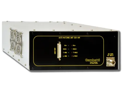
AUTOMATIC MATCHING NETWORK – GGK-AM1

Introduction to adaptation networks In every plasma treatment system, the matching network constitutes a critical component.

The matching network’s purpose is to transform the complex (*) and variable impedance in keeping with the process conditions, in a purely resistive impedance, with a 50 ohm fixed value necessary for the correct operation of the coaxial transmission line and the RF generator. This operation favours the condition of maximum transfer.

The adaptation circuit consists of an ‘L’-type network (but a ‘T’-type configuration can also be chosen) comprising a fixed inductor and a pair of air-variable capacitors. The position of the capacitors is controlled by means of positioning motors.

During operation, commands must be provided via the connector on the front panel.

The matching networks of the GGK-AM1 series provide for the following three methods of operation:

  • Manual operation, in which the position of the capacitors is a function of an external control
  • Automatic operation, in which the position of the capacitors varies automatically according to the impedance characteristics of the load
  • Mixed operation: in which it is possible to keep one of the two capacitors in manual operation and the other in automatic operation.

The second method is fully automatic so, if selected, when the adaptor network detects an RF signal within it, it will automatically search for the optimal operating point in order to achieve maximum power transfer from RF generator to load and does not require the fixed presence of the operator.

The matching network of the GGK-AM1 series consist of an aluminium casing, inside which they are housed:

  • RF signal conditioning circuits
  • Interface circuits with external units, with connector and device status indicators
  • The motors required for capacitor movement

The device is very versatile, as it allows the adaptation of a wide range of load impedances, simply by changing the absolute values of its constituent elements (capacitors and inductor) by means of special ‘pads’ placed inside it.

Product features

  • Compact size
  • Easy operation control
  • Low cost of ownership
  • Flexible architecture allowing the adaptation of a wide range of impedances. Highly repeatable processes
  • User interface providing main information (capacitor position, DC-Bias...)
  • Designed to operate on systems based on 13.56 MHz RF signals
Technical Specifications
Dimensions L x P x A – Footprint 279 x 400 x 112 mm
Net Weight 5 Kg
Respect distances Right, Left – 100 mm, Retro, Fronte – 200 mm
Facility Service RF input connector N-type female
RF output connector Maximum output current 15Amp RF, N female input connector, 7/16 output
Interface connector DB25 socket
Control Interface Power supply 24Vdc, 1 A max (Fuse protected T2A)
Analogue I/O signals 0-10 Vmax
Digital I/O Signals 24 Vdc – inputs provided with optical isolator
Adapter circuit Network type “L’ (optional: other configurations on request)
Operating modes Automatic / Manual / Automatic on single channel
RF Signal Max output Power 600W
Frequency 13,56 MHz
Max. cathode voltage 2000 Vac
Max. cathode DC current 10A RF
Compliance International CE Marked

Form richiesta brochure


  Accetto l'informativa sulla privacy policy.

* Questi campi sono obbligatori.